Seabee construction of new sea and air bases was a vital factor in the success of American naval operations in World War II. As most of the bases were built in undeveloped locations, it was necessary for the construction battalions to bring all of their equipment and a large amount of their materials from the United States. Moreover, it was necessary, at least in the initial stages of each operation, to transfer equipment from ship to shore without conventional port facilities. Chapter VII
Advance Base EquipmentAdvance base equipment fell into two main divisions, standard items available in the domestic market and special items which were developed to speed and ease of construction in forward areas.
Developments in the second category ranged from simple adaptations of commercial items to the invention and exploitation of that wonder box, the universal steel pontoon. An example of simple adaptation was the addition of skids and lifting rings to increase the portability of commercial motor-generator sets. The pontoon was used to ramp construction machinery and fighting tools from LST's to primitive shores; it was powered to provide barge lighterage of goods across shoal water; it was assembled in many forms to perform a great number of indispensable services which could not have been performed as quickly by any other means.
These developments helped in the achievement of a first objective, to get the battalions in working position. Other developments, such as all-water distillation units, were developed so that the battalions could continue working when they were in position.
The story of advance base equipment is told in three parts. The first part gives the details of the major items taken to an advance base by one battalion. The second part summarizes the extra equipment that was supplied to units organized to perform specialized work. The third part described the more important special items as they were developed by the Bureau of Yards and Docks at the Advance Base Proving Ground, Davisville, R.I., and at other places.
Two factors influenced the nature of the equipment taken by the battalions to advance bases -- the climate and advance base construction experience. The climate could be anticipated, and proper equipment to cope with that factor was provided from the start. Construction experience dictated some changes from the original equipment lists, which, in general, had been determined from stateside construction experience. Battalion Equipment
Early battalions were equipped with light and medium weight construction machinery, to ease the task of movement from ship to shore. It was found that the advantage of having the largest units available more than compensated for the difficulties of transporting the heavier items. This was especially important in the more advanced areas of the Pacific operations, where some of the fastest heavy-construction jobs in history were performed.
The first battalions sent into the Pacific were outfitted with "tailor-made" allowance lists. The battalion's complement of equipment and material was determined by the type of work to which it was assigned. The outfitting of a battalion sent to an island to construct a fuel tank farm with fleet fueling facilities would differ from that of a battalion assigned to the construction of an airport. It was soon found, however, that all battalions had similar basic requirements. In order to maintain an efficient working schedule on major construction projects, each battalion was obliged to construct its own camp with facilities necessary for reasonably comfortable living. Island commanders were constantly calling on Seabees for the erection of the living facilities for station personnel, Navy, Army, or Marine. The housing developments, although varying greatly in size, were always
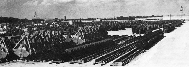
Construction Battalion Equipment at Davisvillesimilar in the type of utilities that went into their make-up -- housing and messing, electrical, water supply, laundry, sewage disposal, and garbage disposal.
Although the primary functions of bases differed greatly, all bases had several facilities in common, such as roads, hospitals, offices, communications, waterfront structures, and storehouses. This fact was borne in mind in the organization of the regular battalions. The personnel complement for each battalion contained the same number of men in the various construction trades. To make it possible for a single battalion to cope with all types of construction jobs, and to utilize personnel as efficiently as possible, the standard battalion allowance list was developed. Whenever experience in the field showed a weakness in some part of the list, the list was changed accordingly. For example, the early battalions had two earth-moving cranes, with a total capacity of three and one-half cubic yards. This was increased in later lists to six machines, with a capacity of four and three-fourths cubic yards. In graders two towed machines were supplied originally. Later, three mechanically controlled diesel-powered motor graders were supplied. In scrapers, the trend was to larger sizes with the same total capacity. The number of dump trucks was increased from 24 to 32. In the following paragraphs the more important items of the 1945 list are described.
In the matter of housing, equipment varied with the climate. The first housing units to be taken to the Pacific were prefabricated huts; later, because of the length of time necessary for the erection of huts, tents were substituted. In the northern regions, the quonset hut was in the original equipment. The construction of quonset huts was varied to adapt them to service in the various climates. The northern units had fixed wood bulkheads, insulation, and windows. The tropical hut had screen bulkheads, screen windows, removable side segments, and a lifting top section that provided additional ventilation.
The 343 tents provided for each battalion were used for all purposes; housing, messing, officers quarters, and storage. Specifically, there were 264 tents, 16 feet square; 21 tents, 17 by 20 feet, and 26 tents, 16 by 50 feet. The quonset hut housing consisted of 72 huts; 69 of the 20-by-48-foot size and 3 of the 40-by-100-foot warehouse size. Enlisted personnel were housed in 56 of the 20-by-48-foot huts, and 10 of the same type were used for officers. One double 40-by-100-foot warehouse was used for galley and messhall. The remainder of the huts were used for storage and utilities.
As the equipment finally evolved, mechanized subsistence equipment for each battalion included eight water purification units, a water supply and distribution system, and when needed, a water distillation system. The purification units had chlorination and filter elements which could provide up to 10,000 gallons of purified water in a day.
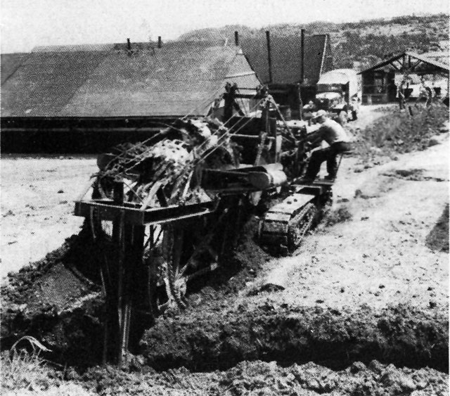
Trenching Machine at Okinawa
Use of these specialized machines speeded the installation of underground facilities at many advance bases.The water was stored in canvas or wood tanks. The fire-fighting system consisted of two 500-gpm centrifugal gas-driven trailer pumps and chemical fire extinguishers.
For electrical power, eight 15-kw three-phase 60-cycle gasoline-driven generators were provided. Communication was handled by a 50-circuit telephone system, a portable field telephone set, and a public address unit. On special request an FM radio station of 30- to 60-mile radius was included in the equipment.
For transportation, 77 trucks, of various types, were included in a construction battalion's equipment. The light trucks were a 3/4-ton ambulance, eighteen 1/4-ton reconnaissance cars (jeeps), and four 3/4-ton carriers. The heavy trucks included one 21/2-ton, six-by-six, 750-gallon tank truck; four 11/2-ton, six-by-six, cargo trucks; four 21/2-ton, six-by-six, cargo trucks; thirty-two 21/2-ton, six-by-six, dump trucks; one 21/2-ton, oilfield body truck, and one 4-ton, six-by-six, cargo truck. In addition to the trucks, there were 20 trailers, of various types, and one fifth-wheel, 21/2-ton, six-by-six truck tractor.
The battalion's earth-moving equipment comprised 37 pieces of equipment. Six crawler cranes included: Two half-yard, 6-ton cranes, each with clamshell and dragline bucket attachments; three, 3/4-cubic yard, 13-ton cranes; and one, 30-ton unit of 11/2-cubic yard capacity, all with clamshell, dragline, and shovel attachments. One of the 3/4-yard excavators was provided with a backhoe attachment.
The tractors sent with a construction battalion were of four classes, ranging from 113-drawbar horsepower to 35-drawbar horsepower. Of the largest size, class one, there were eight. Of classes two and three, there were four each, and of class four, there were two. All these crawler tractors were equipped with either bulldozer or angledozer attachments. These tractors also were used with carry-alls, of which there were eight, four of 8- to 10-cubic yard capacity and four of 12- to 15-cubic yard capacity. In addition to these primary earthmoving equipment machines, there were such items as eight pneumatic rock hammers; one 8-ton tandem and one 12-ton, 3-wheel, gasoline or diesel driven road rollers; one 3-tooth, extra heavy-duty, tractor-drawn rooter; three power graders, with 12-foot blade, 4-wheel drive, 4-wheel steer, hydraulically controlled, diesel engine driven; two 5-ton cargo cranes; two concrete mixers of 7 and 14 cubic feet capacity, respectively; and four portable diaphragm pumps of 3,000-gph capacity.
In addition to the heavy equipment, some construction materials were taken for the housekeeping use of the battalion. A few of the more important items included the following: 1,000 bags of
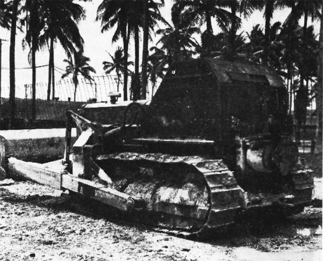
Caterpillar D-8 Tractor with Armored Cab
portland cement, 328,000 board feet of lumber of assorted sizes, 2,800 linear feet of angle and bar steel, 10,850 pounds of reinforcing steel, 14,000 assorted bolts, 65,400 feet of 6-by-19 assorted size wire rope, 120 oxygen cylinders, and 2,550 pounds of welding rod. Thousands of smaller items, hand tools for construction and repair, clothing, small arms, personnel services equipment, combined with the foregoing to make the total for transport.The need for battalions specializing in stevedoring work has been described in Chapter 6. Because these battalions were to engage in construction only to a point of erecting their own camps, they did not need as much construction equipment as the regular battalions. However, their work demanded types of equipment peculiar to cargo handling.
Heavy transportation equipment issued to Specials for cargo hauling consisted of sixteen, six-by-six, 21/2-ton cargo trucks; two six-by-six, 21/2-ton dump trucks; two six-by-six, 4-ton cargo trucks; six 25-ton trailers; and eight 10-ton fifth wheel-type trailers. For handling cargo on the waterfront and in warehouses, twelve fork-lift trucks were included in the complement. Lifting equipment was issued without earthmoving attachments and included four 6-ton and one 13-ton crawler-mounted crane and one 13-ton truck-mounted crane. Crawler tractors were limited to four, two of class one and two of class three, all of which were furnished with bulldozer or angledozer attachments. Eight pneumatic-tired industrial tractors with a load-pulling capacity of 20 tons were shipped for moving trailers.
When the offensive in the Pacific took on larger proportions, the size of naval bases required to support the operations was necessarily increased. For the construction of the larger bases at Guam, Manus, the Philippines, and Okinawa, many battalions were working within close proximity to one another. Special units were set up to provide services which would normally be available to stateside construction forces. In order to avoid duplication of efforts to make major repairs on automotive and construction equipment, and to rehabilitate worn-out tires, specialized units were organized and equipped to handle all work of this type for the construction units in the areas. Dredging was a type of work performed at only a few bases, so a dredging battalion was formed, and detachments were sent where they were needed. Pontoon assembly detachments were developed to build the pontoons from shapes and flat plates. Specialized Units
Projects which were too large to be accomplished with the standardized equipment available with each construction battalion, or which needed special types of equipment, received the regular allowance, augmented by standardized amounts of equipment required. Components were prepared for heavy excavation, rock drilling and blasting, rock crushing and screening, asphalt mixing and placing, lumber production, and port development.
Units, consisting of 20 officers and 630 enlisted men, were provided with facilities for the overhaul of approximately 500 pieces of equipment per month. The shops, ten in number, were well equipped to perform a major overhaul job on all types of advance-base gear, such as trucks, tractors, and cranes. The major special equipment items included a compact trailer-mounted machine shop; a universal boring machine for line and camshaft bearings up to 4 inches in diameter; two clutch rebuilders; four dynamometers; 234 grinders for brake-shoes, crankshafts, cylinders, and valves; two brake-drum lathes; a straightener device for alignment of axles and frames; a test stand for diesel engines, injection pumps, and nozzles; a generator and starting motor test bench; a two-ton bridge crane; and a vertical 36-inch boring mill.
The tire repair units were designed to have a capacity for recapping and top-capping 1,000 tires per week and to make sectional repairs to 1,450 tires in the same period. To accomplish this work, the units were supplied with 20 sectional molds and 15 full-circle molds. The one unit that was put in operation, at Guam, was able to meet the design capacity even though it repaired all the various sizes of tires used on heavy construction equipment, trucks, and passenger vehicles.
One battalion, the 301st, was formed to specialize in dredging. Detachments, each consisting of one dredge crew, were sent any place in the Pacific where their services were needed. The battalion operated standard suction and dipper dredges and numerous smaller pontoon barge-mounted clamshells.
A pontoon assembly detachment, consisting of 17 officers and 418 enlisted men, was equipped to
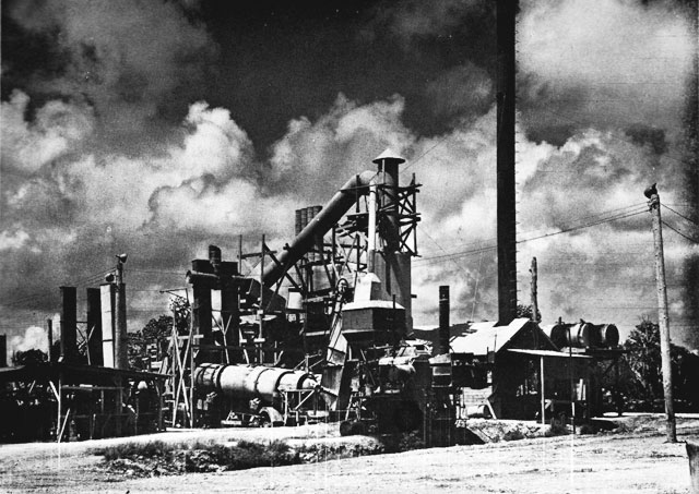
Asphalt Mixing Plant, Guammanufacture about 1,800 steel pontoons per month and to form them into any of the final assemblies. For the assembly of the pontoons, both rectangular and curved types, the detachment was equipped with two assembly lines, consisting of jigs and fixtures to hold the pre-cut plates and structural forms in place for welding.
The heavy excavating and hauling equipment component was designed to handle, under average conditions, 337,000 cubic yards of rock in 30 days. Transportation equipment consisted of four dump-bottom, 13-cubic yard trailers; sixteen 10-cubic yard dump trucks; and twenty six-by-six, 4-ton dump trucks. Excavation machines consisted of six 11/2-cubic yard and three 21/2-cubic yard, crawler-mounted cranes, complete with clamshell, dragline buckets and shovel attachments.
The equipment for rock drilling and blasting was designed to produce approximately 650 cubic yards of rock per hour. The component was composed of seven pneumatic paving breakers; thirty-two 315-cfm and severn 210-cfm portable air compressors; thirty-five wagon-mounted drills; and seven 50-hole blasting machines.
The crushing and screening plant was a portable three unit type with two jaw crushers and one roll crusher, complete with screens, conveyors, bins, diesel-engine power units, and drives. The plant was designed so that a washing attachment could be installed in the third unit, if washed aggregate was needed. The approximate minimum capacity of the plant was 250 tons per hour, of 21/2-inch, maximum size product.
The asphalt plants had capacities of from 110 to 200 tons per hour. Equipment consisted of two 60-HP boilers; a control unit with a 4-by-8-foot vibrating screen; a 24-inch hot-aggregate belt conveyor; two trailer-mounted distributors; a dual-drum type aggregate dryer; a paving finisher with a 10-foot width and a 1/4-inch to 6-inch thickness
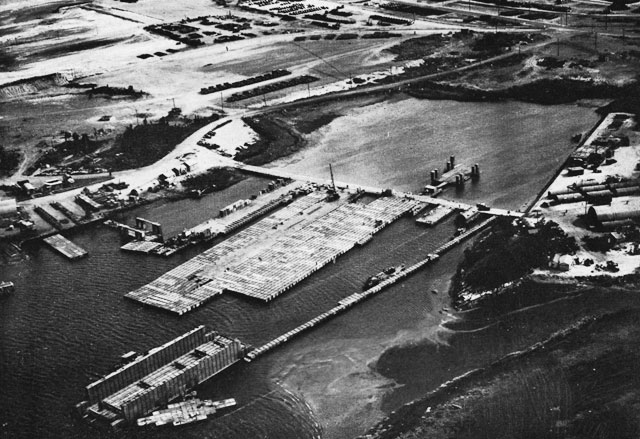
Advance Base Proving Ground, Davisville
Showing various pontoon assemblies. Also note variations in quonset huts (right).working capacity; a crawler-mounted, 3-cubic yard per minute aggregate loader; and a 1,500-gallon asphalt tank.
Five asphalt plants were used in the Marianas in the development of B-29 bomber bases.
The sawmill was a heavy-duty portable type and was designed for installation on permanent or temporary foundations. The complete installation was capable of producing 16,000 board-feet of 1-inch lumber per eight hour working day. The mill was equipped with a 60-inch, circular, inserted-tooth saw, 6-inch belt-feed type, driven by a 148-horsepower engine, underslung chain type sawdust conveyor and 20-foot headblock carriage. A three-saw edger, with 14-inch diameter, inserted-tooth saws, driven by a 100-horsepower engine, and a 42-inch diameter sold-tooth cutoff saw, driven by a 48-horsepower engine, supplemented the main unit to allow production of lumber for all construction needs. Special equipment was designed to augment the allowance of half of a standard battalion to enable it to undertake rapid development of a damaged or undeveloped port. The component supplied two 2-by-12 pontoon bridgers, a 5-by-12 pontoon wharf, and a pile-driver attachment for a 13-ton crane.
To satisfy the requirements that advance-base construction imposed upon equipment, considerable experimentation was carried on at various locations within the United States. Most of the development in materials and equipment was carried on by the Advance Base Department of the Bureau of Yards and Docks in conjunction with the Advance Base Proving Ground at Allen's Harbor, Davisville, R.I. Development of Special Equipment
The Advance Base Proving Ground was an outgrowth of the Quonset Pontoon Experimental Area, which was established before the war. The pontoon
area was under the direction of the War Plans Division of the Bureau of Yards and Docks. Prior to the establishment of the pontoon area, tests of pontoons had been conducted on the Ohio River, at Portsmouth, N.H., and in the Quonset area. In the fall of 1942, the need for a special station, to be devoted to the development and testing of equipment under consideration for purchase by the Bureau of Yards and Docks, became obvious. The pontoon experimental area was the logical site choice. The following objectives were set for the new Advance Base Proving Ground: (1) to assemble and test equipment; (2) to conduct field research of proposed equipment; and (3) to submit recommendations and suggestions for improvements in equipment.Through the war years, the Advance Base Proving Ground tested and developed hundreds of pieces of equipment for Navy use -- distillation units, filtration units, laundry equipment, stoves, propulsion units, trucks and generators, and many pontoon assemblies. However, many improvements in equipment were initiated in the field, either by critical requests for development or by pioneer field improvisations.
The pontoon assemblies were the outstanding items of specialized gear developed by the Bureau in conjunction with ABPG. Assemblies, in the form of causeways and lighters, immeasurably helped troop and equipment landings in Sicily, the Normandy beaches, and in the numerous Pacific islands. Pontoon Gear
The history of Navy lightering pontoon gear invention and development began in 1935 and 1936, when the War Plans Division of the Bureau of Yards and Docks was considering problems connected with the development of advance bases. An officer in the Bureau of Construction and repair, on duty with a western steel company, observed the construction of a sectional barge for use by a dredging company. It occurred to him that this section idea might be of value in connection with the advance-base problem. He sent a drawing to the Bureau of Yards and Docks, showing his idea of how steel box sections might be fitted together to form a barge. These sections were 10 by 20 by 6 feet. The fastening scheme involved bolting adjoining sections together with heavy bolts through holes in the sides, close to the top and bottom plates.
In 1939, Capt. John N. Laycock, CEC, USN, who was on duty in the Bureau, gave the problem further study. As a result, he developed the idea of universal, or uniform size, units which could be fitted together, as needed, to form various items of advance base equipment. Such uniform pontoons might be assembled to form barges, seaplane ramps, and even floating drydocks.
Captain Laycock spent some time in experimenting with a pontoon assembly model made up of cigar boxes, joined together at the four corners by continuous wood strips. The model string showed surprising strength. The unfound key to the pontoon problem, became the system of fastening and assembling. This problem had two elements: first, it would be necessary to find some way to avoid the bending moments which would occur under beam-loading conditions, if the fastening bolts were offset some distance from the top and bottom plates. Second, it would be necessary to provide some means of making strings of the pontoons so that small assemblies could be launched.
The problems were solved by the use of continuous angles, analogous to the wood strips in the model, fastened to the boxes with bolts and wedges. Room for a connection between the angles and the boxes was made by cutting off the corner of the box and closing the triangular opening, thus made, with a plate. A punched connecting angle strap was then welded to the box at the lopped-off corner.
With the method of assembly adopted, the only feature which remained to be determined was the size and structural form of the pontoon.
The criteria established were as follows: (1) the width of the largest plate used could not exceed the width of plates usually rolled in large quantities; (2) the width of a string of pontoons would have to be great enough to allow stability when afloat; (3) the limiting light weight of a pontoon should be one ton; (4) the top surface of the pontoon should be capable of supporting a ten-ton load from each of two dual tires; (5) a pontoon when full of gasoline should weight about 5 tons, the normal capacity of cargo booms on merchant ships; (6) there should be a total width of about 20 feet when three strings were assembled side by side; (7) the draft of a pontoon when unloaded should be about 16 inches. From these criteria, trial and
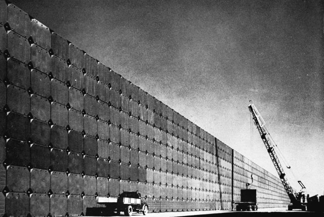
Pontoon Stock Pile at Port Hueneme
These steel boxes carried the tanks from the LST's to the beach, docked the small ships, barged the freight, and bridged the stream. More than thirty standard assembles were developed, and may others reached at least the experimental stage.error studies indicated the dimensions should be 5 by 7 by 5 feet. The steel box was stiffened by 6-inch plates, welded together to form a T and welded girthwise to the interior of the pontoons.
The first test of a pontoon string used eleven pontoons, set up as a bridge simply supported at the ends, with a load concentrated upon the center pontoon. The test was carried out by using steel plates as the elements of the test load. Failure occurred when the load reached 55 tons, one of the lower angles failing in tension at that load. Other tests were conducted on a 3-by-7-pontoon barge, a small drydock assembly, and a seaplane-ramp assembly.
With the pontoon in satisfactory shape for use, there remained the development of some form of propulsion unit. Three possibilities were studied: A paddle-wheel unit, an outboard unit, and an inboard unit. The outboard unit was the one selected. An experimental model was made and given a performance test at Quonset Point.
From these basic beginnings, various assemblies were made, including net tenders, warping tugs, causeways, RHINO ferries, 75-ton floating cranes, drydocks, finger piers, seaplane service piers and ramps, and an experimental aircraft landing field. The 1944 Pontoon Gear Manual, published by the Bureau of Yards and Docks, listed 31 standard assemblies.
The pontoon, in its final World War II form, had quarter-inch plates at the top and bottom, and 10-gauge metal (about one-eight inch) for sides and ends. Inside, they were braced to withstand an internal pressure of 25 psi. The pontoon weighted 2,000 pounds, and the various connections added 800 pounds. The net buoyancy capacity of each pontoon was about four tons, but the payload was limited to one long ton. There were three types of pontoons: the 5-by-7-by-5-foot, for universal use;
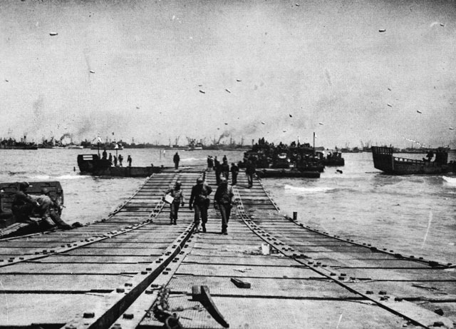
Pontoon Causeway in Use in the Normandy Invasion
Landing craft, in the background, tied up and unloading.the curved-bow pontoon, for transport service; and the wedge-box pontoon, for landing use. The pontoons were assembled into three standard sizes of barges: three by seven, 50-ton; four by twelve, 100-ton; and six by eighteen, 150-ton. Other types were made as required. Cranes, gasoline tanks, drilling rigs, pile drivers, and similar equipment were mounted on these barges.
For PT-boat service, a fixed-boom assembly was mounted on a 6-by-18-pontoon barge. This unit permitted a 66-foot, vertical, one position lift of 75 tons. It was used to lift PT boats from freighters.
The method of pontoon causeway placement under fire was notable. Strings of pontoons were slung on either side of an LST, in a cradle that was secured by ropes. At the proper time during the vessel's approach to the beach, Seabees chopped the stay ropes. Th strings plunged into the water and rode to the beach under momentum. For a 300-foot causeway, one string was beached and the other overlapped the outboard end of the beached string. In an experiment at Allen's Harbor, this complete operation took only seven minutes from the time the ropes were cut until the first vehicle rolled from the bow of the LST onto the causeway.
These pontoon causeways as a decisive factor in the Sicilian invasion are discussed in Part III of this history.
A pontoon experiment which did not reach combat use was the floating airfield. The experiment was conducted at Davisville, to develop an airfield for British use. The assembled flight strip was 1,800 by 175 feet, with two 50-foot parking strips. It was towed and anchored in a cove of Narragansett Bay. For a day, airplanes successfully
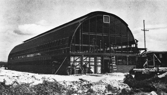
Quonset Warehouse Adapted as Two-story Barracks for WAVES, Oahuused the pontoon field. Then during tests in open water, damage occurred to minor parts, and experimentation ceased.
Pontoon drydocks were made in many sizes. Standards established for units varied from four strings of 15 pontoons to thirty strings of 12 pontoons, each. In assembling the drydock, the strings of pontoons ordinarily were connected to parallel the keel of the vessel on the dock. In the 30-by-12-ponton dock, however, the string of 12 pontoons was placed at right angles to the keel line, thus giving maximum strength crosswise. Wingwalls were discontinuous towers of pontoons in some drydocks; continuous, in others.
When drydock pontoon strings were assembled, a short piece of 2-inch pipe was swiveled to an opening near the bottom of each pontoon by means of an ell. Standard air hose couplings were put at the top lug of each pontoon and connected to hose lines from a tender barge. When the drydock was to be submerged, the inlet pipes were lowered to a horizontal position in the water, and the dock was submerged by opening valves in the air lines and permitting the water to displace the air in the pontoons. When the drydock had submerged to the depth desired, the valves were closed. When it was desired to raise the dock, compressed air forced out the water. After the dock floor was above water, the mouths of the 2-inch inlet pipes were lifted to a near-vertical position, to avoid the possibility of unintentional flooding.
Adjustable boat supports were provided to fit the keels of small vessels, and catwalks were built across the spaces between the discontinuous tower pontoons, to facilitate handling of lines during the docking of a boat. PT boats and seaplanes were regular users of the smaller floating drydocks of this type.
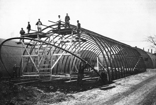
The quonset hut, whose semi-cylindrical form was copied from the British Nissen hut, by the end of the war differed considerably in construction from its prototype. The original quonset hut was framed with arch-rib members of steel, T sections, 2 inches by 2 inches by 1/4 inch. The hut was 16 feet by 36 feet in plan. The members were formed to a radius of 8 feet and covered with corrugated steel sheets, borne by wood purlins. The principal improvements over the Nissen type were an interior pressed-wood lining, insulation, and a tongue-and-groove Quonset Huts
School Hut at the Central Spare Parts Warehouse, Joliet, Il.
Showing the erection of a 40-by-100 foot quonset hut in the Seabee camp area.wood floor. Innumerable detail problems were encountered in the development of the original T-rib huts, principally because of the necessity for developing types to care for 48 different needs, such as galleys, shower-latrines, dental offices, isolation wards, and bakeries. Each type required individual drawings and layouts for the interior setup, and in many cases it was necessary to develop special interior equipment, such as special ovens and beds, to fit the quonset-hut form. All huts were designed and detailed, using the original T-rib design.
The principal objection to this type of construction was that the curveline of the side walls began at the floor resulting in a loss of effective width of the hut. A more suitable structural rib was found in the form of a welded strip steel member, 2 inches by 35/8 inches. This member -- actually, two light-weight channels welded back to back -- contained a groove which held nails. The new rib was fabricated to provide a vertical side-wall, 4 feet high. This new hut was known as the quonset redesigned hut. Its floor plan was 16 feet by 36 feet. Standard hut drawings were remade, for both structural and facility details. As the necessity arose for adapting the huts to use as dispensaries, latrines, hospitals, and other special facilities, the details were worked out and checked by actually erecting units in the field at the proving ground, to determine the practicability of the design for field use. In all, 86 approved interior layout plans were prepared for the small hut and the large 40-by-100-foot arch-rib warehouse.
To reduce shipping space and tonnage a redesign, incorporating lighter, corrugated, galvanized sheets for covering and half-inch plywood floors instead of one-inch tongue and groove, was effected. The new hut was larger, 20 feet by 48 feet, and lighter, using 31/2 tons of steel instead of 4 tons. It occupied from 270 to 325 feet of
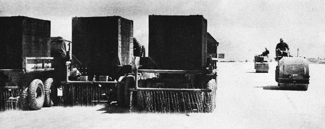
Pontoons Rigged as Sprinkler Tanks on Dump Trucks
Sprinkling freshly laid coral flight strips on Okinawashipping space instead of 450 cubic feet. The arch-rib again became semi-circular.
Toward the end of 1943, continuations to each end of the hut added 4-foot overhangs to the 48-foot length. The addition was to prevent driving rains and sunlight from entering the hut through the end bulkheads. The total outside length of the hut became 56 feet, but the actual interior living space remained 48 feet. The official quonset hut dimension nomenclature than became 20-by-56. However, in the spring of 1945, it was determined that the 4-foot overhangs on the huts used in northern or temperate climates were unnecessary, and they were eliminated. In order to standardize the nomenclature for both the northern and the tropical type the dimension nomenclature was changed back to 20-by-48. This, of course, was based on interior, living dimensions; the exterior dimensions of the tropical hut remained at 20-by-56. Throughout this war history, with few exceptions, when quonsets are referred to they are of the 20-by-48-foot living-space size.
As finally developed, the quonset hut required less shipping space than did tents with wood floors and frames, when equal numbers of men were to be accommodated.
Originally, all huts had unpainted galvanized exteriors. To reduce the chance of enemy observation from the air, an olive-drab camouflage coat of paint was applied at the factory. After 1942, the factory service was extended to include packaging for overseas shipment. Before then, some plate bending, wood fabrication, and all packaging took place at Davisville.
The number of huts produced or procured by the Navy were as follows:
T-rib quonset 8,200 Quonset redesigned 25,000 Quonset 20-by-48 and 20-by-56 120,000 153,200 Larger warehouse structures also were developed for Navy advance base use. The first were 40-by-100-foot structures with vertical sides. They used 20 tons of steel and about 650 cubic feet of shipping space. About 300 of these were procured. They were superseded by a quonset-type warehouse of the same floor plan. The steel weight was 121/2 tons, and the shipping volume was 350 cubic feet. If a concrete floor was required, 600 additional cubic feet of shipping space was required for portland cement. In all, 11,800 such warehouses were procured. For large advance base supply functions, multiple arch-unit warehouses were developed from the 40-by-100-foot warehouses, to furnish greater storage area under single roofs.
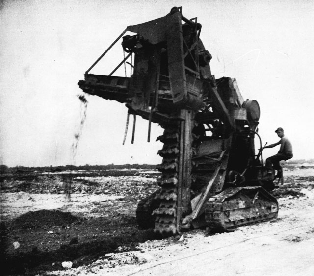
The pontoon and the quonset hut were the most Water Treatment
Bucket Ditcher Excavating Drainage Trench to Handle the Tropical Rains of Peleliu Islandspectacular of the Bureau's developments during the war. Many other developments also contributed to the efficiency of the construction battalions. Much of the work done at the proving ground was undertaken in an effort to improve on existing commercial equipment and to adapt it to advance-base use. Five outstanding types of equipment were adapted; Water-supply equipment, refrigeration units, laundry units, galley equipment, and electrical equipment. Most of the development was in the direction of making this equipment into portable units which would have sufficient strength to withstand the abuse of shipment and rough operation.
One of the most essential types of equipment was that used to produce pure water from surface water, ground water, and/or sea water. The water might be relatively free from contamination, salty or brackish, or high turbidity. Filtration, hypochlorination, or distillation were used, depending upon the type of water available.
The first of these treatment systems involved a process of coagulation and sedimentation, filtration, and chlorination. The coagulation and sedimentation unit was used to remove most of the turbidity and some of the disease-producing organisms; the filter removed the remainder of the turbidity and more of the disease-producing organisms;
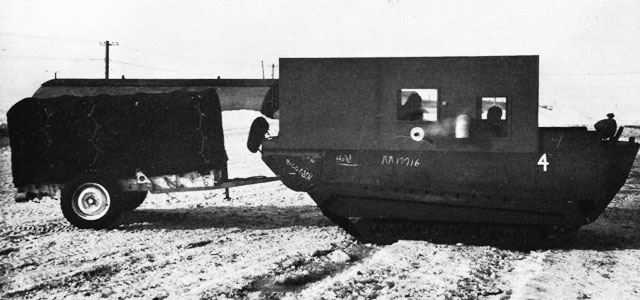
Amphibious Tracked Cargo Carrier, Alaska
Adapted for use in the Arctic.chlorination destroyed remaining bacterial contamination.
The filtration equipment originally provided was of the rapid sand-filter type, working under pressure. Later, a portable diatomite-filter unit was developed, which produced a high quality of water with positive protection from amoebic contamination. The chlorination equipment was a positive-feed type, which applied a calcium-hypochlorite solution to disinfect the water prior to consumption.
The equipment for the first method was a combination of the three purification elements (settling tank, filter, and chlorinator). It had a total weight of 2,176 pounds. The settling tank was a 3,000-gallon canvas tank. The unit, 31 inches by 25 inches by 37 inches, incorporated a skid-mounted gas-driven pump and chlorinator. The filter was an 18-inch diameter tank, 36 inches high. The entire system was connected with linen hose. It could be operated by one man.
The second of the treatment methods, hypochlorination, was not intended to be used with water of high turbidity, because no settling or filtration was included. In its simplest form, lister bags or chlorine pills in canteens were used.
For a larger system, a hypochlorination unit was connected in the purification line at the entrance to storage tanks. The unit, 25 inches by 28 inches by 25 inches, was skid-mounted.
The distillation method was used where a sufficient quantity of fresh water was not available. In the early days of advance base construction, the distillation equipment provided was of the double-effect type. These units, similar to shipboard installations, produced a pure water, but they were complicated to operate, had excessive weight and low economy. This type of distillation unit burned either diesel oil or gasoline. To overcome the disadvantages of the double-effect still, the Bureau sought a better unit. The result was the vapor-compression unit. The basic element of the new system was a gasoline or diesel engine which drove a vapor-compression pump, a condenser, and a flash tank. The distillation process used the engine heat to raise the temperature of the raw water to a point where it would flash into steam in the flash tank. From the flash tank the vapor was pulled into the compressor, which delivered the vapor to the condenser. After condensation, the liquid was drawn from the system and stored.
This unit was particularly adaptable for use during landings, because of its medium size (about 5,000 pounds), its simple operation, and its efficiency (150 pounds of water delivered per pound of fuel). The first of these models was produced
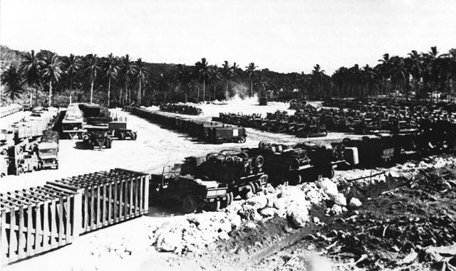
Construction Equipment Pool in the Russell Islandsfor the Navy in 1943. After 1943, it dominated the distillation picture as far as use in initial advance-base movements was concerned.
For advance base purposes, two distinct designs of refrigerators were developed. The first was a self-contained unit with a storage capacity of 150 cubic feet This box had plan dimensions of 6 feet by 8 feet 6 inches, and it stood 5 feet 6 inches high. It could be operated on gasoline or electricity; it was weatherproofed so that it could be moved from place to place. The second type of refrigerator was the walk-in, knock-down type, 675 cubic feet and 6,800 cubic feet capacity. The knock-down types were used in quonset huts and temporary buildings. These units were electrically operated; one-panel units were used on the small size (9 feet by 14 feet), and eight-panel units were used on the large one (12 feet by 96 feet). The knock-down refrigerator was pre-fabricated in sections which could be assembled in a large number of overall sizes, depending upon requirements. When it was necessary to move the knock-down refrigerators, Seabees disassembled them and reerected them at the new location. Refrigerators and Galley Equipment
In galley equipment, the picture was largely commercial. One change, however, was effected in coffee urns. it was found that the electricity consumption was too high for economical use with portable generating equipment. A gasoline-fired heating element was substituted.
The laundry equipment used by the construction battalions was also portable. Several types, all of which were adaptations of commercial equipment, were used in the field. The first of these units was a 75-pound-per-hour machine of three skid-mounted units. The first section was a power unit, a boiler that produced both steam and hot water, and a five-horsepower steam engine. The second was a washer and an extractor. The third was a tumble-drier unit.
This washer was satisfactory except that it was difficult to obtain accurate alignment of the driving shafts from the power unit through the other two
units. Another laundry unit was developed by a commercial concern and improved at the proving ground. It had separate electric drives for each of two units. One unit included the boiler and washer; the other, included the extractor and the tumbler. This design was lighter in weight than the first. It had an oil-fired tumbler, only two skids, and there was no alignment problem. It provided insufficient hot water, but an addition to the boiler filled that deficiency. Proving-ground development on this piece of equipment was the oil-fired tumbler.Electrical equipment also was adapted from commercial items. In the case of the power-generating units, adaptation required construction of a portable skid base, a protective metal housing, hooks for lifting, and electrical coupling connections to meet the requirements of portable use. The sizes used at advance bases ranged in capacity from 1 kw to 300 kw.
Table of Contents
Previous Chapter (6) * Next Chapter (8)