SUBMARINE SQUADRON FOUR
U.S.S. Argonaut, Flagship
Submarine Base, Pearl Harbor, T.H.
FF12-10(94)/S1
26 DEC 1941
Serial 0570
CONFIDENTIAL
| From: |
The Commander Submarine Squadron FOUR. |
| To: |
Chief of Naval Operations. |
| Via: |
(1) The Commander Submarines, Scouting Force.
(2)The Commander-in-Chief, U.S. Pacific Fleet. |
| |
| Subject: |
Japanese Midget Submarine, No. 19.,
Description of. |
| |
| Enclosure:: |
(A) Photographs and Data. |
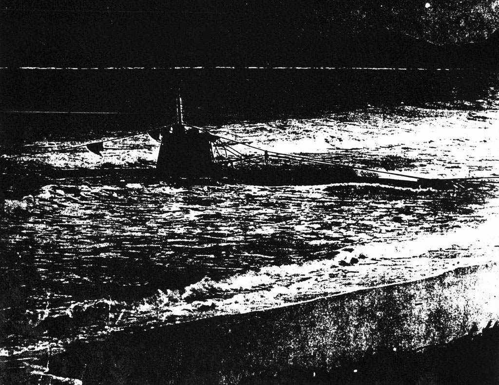
1. Enclosure (A) herewith is the description
and photographs of the Japanese Midget Submarine No. 19.
2. On Monday, 8 December, word was received
that a Japanese submarine was aground on the reef off
Bellows Field, Waimanalo, Oahu. The Commanding Officer
had abandoned his ship when it struck the reef, and had
swum ashore, and was captured. His crew, consisting of
one man, had abandoned ship at the same time. What was
iodentified as his body drifted ashore the next day.
3. A salvage party from the Submarinen Base
was sent to Bellows Field. Army planes had bombed the
submarine, doing no damage, but had broken her loose
from the reef, allowing her to drift inshore. The
sallvage pargy hauled the submarine in, secured her, and
made an examination. The bow net cutter, propellers,
and rudder had been damaged in the reef, otherwise the
submarine was intact.
4. Plans for salvage were made. A demolition
bomb in the after battery compartment was removed. It
was found that the submarine consisted of three sections
bolted together. By the aid of a jury mast, a heavy
s;ed pf 12" × 12" timbers, and an army tractor, the
submarine was hauled higher on the beach. After considerable
effort, the three sections of the submarine were unbolted,
placed on trailers, and hauled to the Submarine Base.
/Signature
illegible
GENERAL DESCRIPTION OF HULL

1. Hull is made of ¼" cold rolled mild steel (10" plate) and
is divided into 3 sections, namely:
TORPEDO ROOM -- 18' long -- bolted to center section -- contains:
Two 18' torpedo tubes mounted one over the other.
Torpedo war head 6' long containing approximately
1000 lbs., explosive.
The only ballast tank which is 7'5" long.
2 H.P. air flasks, and two impulse tanks.
Torpedo tube firing valves.
250 led pigs weighing 2766 lbs.
CENTER SECTION -- 35'1" long -- 6'1½" maximum
outside diameter -- contains:
Three compartments separated by W.T. bulkheads with doors.
FORWARD BATTERY -- contains:
H.P. air and oxygen flasks on port side.
One fourth of entire battery.
90.5 gallon trim tank under battery.
Air purification.
284 lead pigs on port side forward weighing 3133 lbs.
CONTROL ROOM -- contains:
All depth and ship control instruments.
Small crystal controlled radio.
Periscope.
Torpedo tube controls.
Gyro compass.
Electrically actuated directional gyro.
Small electric trim pump.
H.P. air manifold.
Small regulator tank.
Hydrogen detector.
AFTER BATTERY -- contains:
3/4 of entire battery (36 cells).
Sound equipment.
Air conditioning apparatus.
Air purification.
56.5 gallon trim tank under battery.
MOTOR ROOM -- 24'10½" long toend of propellor hub,
bolted to center section -- contains:
Motor control panels.
Motor.
Gear box.
Small free flooding tank.
Tail assembly.
2. CONNING TOWER -- 5'6" high to top of periscope shears,
mounted directly over control room, contains:
Small tube leading to hatch which can be opened from inside only.
Periscope.
2. CONNING TOWER -- (Continued).
Vertical rubber covered radio antenna 32" high
just forward of conning tower hatch.
Two white lights, one forward (screened), one aft.
Telephone jack connection for outside communication.
A U-Frame fairing periscope sheers from forward
net cutting clearing line to top of shears.
Battery ventilation exhaust.
No bridge.
3. PERISCOPE -- 10' long, 3 5/8" diameter, Japanese make buy
almost an exact copy of our Zeiss 30' periscope, two magnifications
1.5 and 6.0, raised and lowered by electric motor.
4. The directional gyro was mounted in the control room
amidship and alongside of the gyro compass. It was visible from the
conning tower hatch. It had a 3" card which had cardinal and intercardinal
points figured in luminous paint.
5. The gyro was of Japanese make similar to ANSCHUTZ gyro
(described, page 224 article 135 in Applied Gyrodymanics by E.S.
FERRY, 1932 edition.
6. Boat contained 6 H.P. air flasks with total capacity
of 1290 liters at 230 kg.sq cm (45.54 cu ft at 3271 lbs per sq inch).
There was one oxygen flask of 1.33 cu.ft. capacity.
7. PROPULSION -- entirely by battery, no diesel, outside water
proof charging connections, battery approximately 192 volts 2250 AH
capacity one hour rate.
8. DISPOSITION OF MATERIAL:
Torpedoes complete with warhead and exploder
turned in to NAD Luelualei.
Radio to CinCPac radio officer.
8. DISPOSITION OF MATERIAL: (Continued).
Sound gear to S/M Base.
All charts and articles of interest CinCPac
Intelligence officer.
H.P. air flasks to Diving and Salvage unit P.E.
9. Tests on all gear, including batteries, and motors will
be conducted by S/M Base and separate reports made. Separate reports
will also be made on analysis of hull materials and operations of
gyro compass.
PROPELLORS:
| Two propellors, mounted in tandem, forward turns right
handed, after turns left. The propellors are protected
by a hoop propellor guard and skegs. Screws are aft of
stern planes and vertical rudder. Tail assembly so arranged
and faired as to offer no projection to catch on net. |
| |
 |
DESCRIPTION OF TORPEDO TUBES AND FIRING MECHANISM
TORPEDO TUBES NOS. 37, 38.
1. TUBE BARRELS:
Two torpedo tube barrels about eighteen feet in length are mounted
vertically on the centerline in the bow, separated by about ten inches.
The barrels are built up from three sixtreenths steel plate, welded and
riveted. Vertical and horizontal lands of three eights inch brass
strips one inch wide extended about two thirds the length of the barrel
from a three inc h wide circular bearing plate at the muzzle. The top
and bottom lands consists of two strips about five eights of aninch
apart thereby providing a top and bottom guide slot to receive the guide
studs on the torpedo and in additon to receive the guide studs built
upon the vertical shoes of the torpedo.
The breech section is a semi-spherical casting riveted and welded to
the barrel and containing a housing for the impusles air check valve and
an adjustble tail stop with a thich rubber buffer. The torpedo is
muzzle loaded. The clearance between the torpedo and the tube lands is
about one sixteenth inch.
2. SETTING SPINDLES AND STOPS:
The tubes are provided with gyro and depth setting spindles,
engaged and disengaged individually at the tubes, but turned for
simultaneous setting by mechanical linkage and shafts to the control
room. The torpedoes and depth indicator dial in the control room
indicated a five meter depth setting. Gyro singles were zero.
The stop bolt located on the top of the tube and the tropping latch
are mechanically lifted and lowered by an operating shaft atthe breech
section. On firing, the stoip bolt is lifted by an air piston. The
tripping latch housing inspected, was packed with fresh white lead and oil.
3. DRAINAGE AND VENTING:
Located near the breech end are individual three and one half inch
copper flood pipes and one inch copper vent pipes leading outboard.
The tubes are free flooding and venting.
4. TUBE FIRING:
The tubes have individual impulse tanks of 69.4 litres volume.
Impulse pressure was not indicated. Two and three sixteenth copper
impulse pipes lead from the tanks directly to the firing valve. On
the valve housing is a small reducer with two copper service lines to
the tube firing system. It is not possible to give a detailed account
of the firing system without dismantling the entire torpedo room. It
appears that there is a system of air piston interlocks operated by
service air for each setting spindle and leading to the control room so
that when tube is fired, service air goes to a "stop cylinder", lifting
the stop bolt and releasing impulse air built up against the firing
valve. Mechanical lugs and screws prevent operation of the stop
cylkiner unless the stop bolt and tripping latch are in the proper
position. The action of the firing valve follows: The main valve of
steel and cup shaped, is about two and three sixteenths inches in diameter
and is held on its flat seat by impulse air, gravity and a large
spring. This valve has a one inchh hole in the center of its face and
provide a flat seat for a brass, so called, "auxiliary" piston valve.
When air is released in the chamber of the piston valve, the valve
lifts, thereby desroying the balance of forces holding the main valve
on its seat and causing it to lift. A tapered lug integral with the
loer face of the piston valve, controls the tube pressure and too
rapid lifting of the main valve. A mechanically operted screw sleeve
in the valve bonnet closes the line leading to the "stop" cylkinder,
when it is in the down position. An arrangement like this is necessary
to charge the impulse line and in addition acts as a safety stop valve,
no impulse sotp being provided.
It is understood tha the Captain of the submarine tried to fire the
tubes but couldn't. The above mentioned screw sleeve was found in the
closed position, preventing firing of the tube.
ANALYSIS OF DEMOLITION CHARGE IN AFTER BATTERY #19
DEMOLITION CHARGE FOUND IN JAPANESE SUBMARINE:
DETONATOR:
|
|
|
| Name of product: |
|
SHIMOSE pvisue (Hexagonal) powder no 7. |
| Powder type: |
|
SHIMOSE blasting powder. |
| Detonator: |
|
Made November 1941. |
| (Rest): |
|
Made May 1938. |
| Item: |
|
No 679. |
LONG CENTRAL CHARGE BELOW DETONATOR:
|
|
|
| Powder type: |
|
SHIMOSE pvisue (Hexagonal) powder #2. |
| Item: |
|
No. 474. |
| Made: |
|
October 1934. |
| Cast: |
|
September 1935. |
| Remade: |
|
November 1941. |
SHORT CENTRAL CHARGE BELOW DETONATOR:
|
|
|
| No: |
|
SHIMOSE pvisue (Hexagonal) powder No. 1 long. |
| Item: |
|
No. 67. |
| Made: |
|
October 1905.
Navy SHIMOSE powder arsenal. |
TRAPEZOIDAL SHAPED POWDER CHARGES:
|
|
|
| Name: |
|
SHIMOSE pvisue (Hexagonal) powder. |
| Item: |
|
# 474. |
| Made: |
|
October 1934. |
| Cast: |
|
September 1935.
Navy Powder Arsenal. |
HOLLOW WOOD OR PLASTIC TOWELS CONTAINING DETONATOR:
|
|
|
| No: |
|
SHIMOSE pvisue (Hexagnal) powder #5, Empty towels. |
| Item: |
|
No 65.
Naval SHIMOSE Powder Arsenal. |
| Repaired |
|
June 1926.
YOKOSUKA Navy Yard. |
COPY OF NOTES MADE ON CHART BY COMMANDING OFFICER NO 19.
ATTACK LOG
| 1300: |
Finished final operation (preparation ?) of tubes. Towering
waves (came aboard ?). |
| 1500: |
Sighted OAHU ISLAND. Sighted radio station's red light and
Island's __________ L 20°.
This ship 90°. |
| 1615: |
Sighted Barber's Pt. Lt. electric light L 40°. |
| 1800: |
__________ ships 2 @25m. |
| 1815: |
According to Intelligence, ships in harbor as follows:
BB5 Battleships 5, Light cruisers 3.
Destroyers 16 entered harbor.
HONOLULU HARBOR: Light cruisers -- 4 boats.
Destroyers -- 5 boats.
| Within |
1m |
| 5 L+ |
180m |
| 7 |
220m |
| 12 |
430m |
Things to be taken along at time of departure:
Number 1: (Weather smooth. time of hitching to mother ships
crane (or) lying alongside mother ship.
Stop watch. Sabre. Pistol. 2 Mirrors. Important kinds (?)
tools. Duffle bag. Wool blanket. Life collar. Personal,
things taken along: Life collar clothing:
PEARL HARBOR
Number 2: (Weather rough ...)
Sabre Pistol
Life collar
Clothing: Naked. |
|
Stop watch
Important kins (tools. |
|
| 8th December: |
| |

Absorption care (for) 2 men (to last for) 17h. Smallest
attack distance 250 m.
|
| |
Taking care of ship's air: 2 men.
CO2 (in) 3h will be bad.
C2 (in) 4.5h will be insufficient.
Leaving time.
Sinking signal D.
5 go.
11.5 stop. |
COPY OF NO 19 COMMANDING OFFICERS LOG AND NOTEBOOK.

| NO 19. |
1. |
Emergency tank vent. |
| |
2. |
Balloon bulb (?) (or "valve"). |
| |
3. |
Illuminating light globes -- we lack 2. |
| |
4. |
Adjust the ballast. |
| |
5. |
Emergency valve air leads excessive (put in air). |
| |
6. |
Safety valve bolts. |
| |
7. |
There ws no bolts for ? . |
| |
8. |
No stop pins for wave (?) mast. |
| |
9. |
Triclination (?) heavy. |
| |
10. |
Vertical motor rudder ? . |
| |
11. |
Triclination switch valve heavy. |
| |
12. |
Depth gauge (?) adjustment will not turn. |
| |
13. |
No stop pins (for) ? . |
| |
14. |
Oil leak from oil pump. |
| |
15. |
Water pressure valve no good. |
| |
16. |
Water leak from valve that adjusts air. |
| |
17. |
No stop needle (right & left) on inclination gauge. |
| |
18. |
Bolt on water valve (high(pressure)? air). |
| |
19. |
Periscope pin. |
| |
20. |
Hard to release oxygebn. Put water into ? tube
of regulating valve. |
| |
21. |
Hydrogen indicator. Thermometer, flap (?) needle. |
| |
22. |
Heavy when floats. |
| |
23. |
Air leak in valve (for) compressed air. |
| |
24. |
Air leaks (at) horizontal rudder connection. |
| |
25. |
Big water leak. |
| |
Main points: |
| |
|
Depth angle. Right turn -- shallow.
Depth angle. Left turn -- deep. |
| NO 17 |
1. |
Equipment for raising and lowering periscope.
Motor noise is loud. |
| |
2. |
There are no bolts for ? .
Inspect oil for torpedo tubes. 0.2K
Supplementary tank. 0.5K
2 Pressure gauges.
Tools for building ship.
Tool box for periscope.
? .
Additional things.
2 net cutters. |
| |
(December) 4th. |
| |
|
Get the radio ready.
Load on a small battery.
Examine the charging control. |
| |
(December) 5th. |
| |
|
Air for the (torpedo) tubes. Examine the air.
Draw out the torpedoes. Add oxygen. Trim the charge(?) |
| |
(December) 6th. |
| |
|
Load on the goods to be carried.
Adjust the radio.
Band thrown off. Vertical and Horizontal rudder.
Charge. Compensating (tank?) 1 Note.
(See) whetherh or not water was leaked in. |
| |
(December) 7th. |
| |
|
Put on net cutter.
Take off ? screw.
Load up and leave. |
| |
Front 240 |
| |
Rear 210 |
| |
Wheels Radio |
| |
High pressure. Oxygen. |
|
| |
Torpedoes. Otherwise (?) in good shape. |
| |
(December) 7th. |
| |
|
I have many recollections from my childhood. Today
I will shoulder one important mission and, diving
into ______ Harbor, will sink the enemy's warships. I
was born a man in our country and the presnt daring
enterprise is really the peak of joy (for me).
Disregarding the hardships and bitter dangers of the
past year, I hve trained __________, and (now) the time
has come when I will teset my ability here.
These (torpedo) tubes are the pick of our navy. Moreover,
they are the result of the wisdom and skill of
several tens of thousandsn of Japanese. In the present
operation the strength of the crew is even more
prepared than the torpedoes and certainly we are all
completely affected by a (feeling) of self sacrifice. |
| |
5 Absorbtion (soda lime) cans.
2 Electric lights.
Necessary tools and equipment.
Pistol (ammunition).
23.6 K+ |
| |
4 primers.
Make a trial ignition. |
| |
Spare batteries Ash (?) can.
Large style electric lights.
Hydrometer chart of right and left curves. |
| |
|
| |
2 blankets.
Firing angle chart.
Chart of ship types.
Flight chart ______ 1.
Military charts ______ 2.
Necessary tools.
Double mirror. |
4.8 K
Chart of standces.
Stop watch.
Eye band. |
|
| |
Medical supplies.
Alcohol. |
| |
Equipiment carried along: |
| |
Names of warships (?). |
| |
?
Knife (?)
? |
Cigarettes
Sabre
4.5K |
Matches.
? |
|
| |
|
| |
|
| |
|
| |
|
| |
|
| |
|
| |
Necessary tools for ?. |
| |
Rations |
| |
|
Flight rations.
Pure water.
Fruit.
Alcohol. |
|
chocolate.
dry bread.
|
| 2.6 K |
|
| |
| MEASURING ELECTRICITY. |
| Hydrometer (?) |
1.025 |
| Compensating tank. |
0 |
| #1 tank. |
0 |
| #2 tank. |
100 ? |
| #3 tank. |
200 ? |
| Air. |
230 K |
| Oxygen. |
200 K |
| Lubricating oil. |
29 ? (full) |
|
| |
Lubrication. |
| |
| |
(Upper tube). |
|
|
| |
Left 30° |
30° |
0 |
| |
Right 30° |
27° |
-2° 30' |
| |
(Lower tube) |
|
|
| |
Left 30° |
26° 30' |
-3° 30' |
| |
Right 30° |
25° |
-5° |
| |
? |
Advancing inclined. |
| |
100m |
1° |
|
|
| |
| Battery room in aft part. |
|
F44 |
| Battery room in aft part. |
|
F36.5 |
| Control room. |
|
F3c |
| Battery room in fore part. |
|
F29.5 |
| Control room. |
|
F31.5 |
| Battery room in fore part. |
|
F27.5 |
| Battery room in fore part. |
|
F26.5 |
| |
| Blasting powder. |
|
45K |
| ? |
|
34K |
| Rations. |
|
15K |
| Medical goods. |
|
10K |
| Double mirrors. |
|
5K |
| Pistols. |
|
|
| 2 blankets. |
|
5K |
| Pure water. |
|
5K |
|
| |
Rudder limitation. |
| |
|
| 500 mm |
10 mm |
|
| Greatest rudder capacity { |
123 mm
123 mm |
| Emergency valve. |
|
|
| |
Retaining (?) needle (from 106?) full turns) (1) 0.5 mm. |
| |
Movement enough (?) 16.5 mm. |
| |
Fixing inclination 16mm. |
| |
Fixingn depth angle 10 mm. |
| |
Angle of inclination 20 within water. |
| |
Valve to decrease pressure 30 mm. |
| |
Safety valve (on?) some 40 mm. |
| |
Lowest degree at which oine can live -10%. |
| |
Poisonous over 60%. |
| |
Proper account 18-25%. |
| |
Time for raising and lowering (periscope?) 9-10 seconds. |
| |
Examination of air inside 0.75 cm. |
| |
Examination of lubricating (oil?). |
| |
Tank - 1 ? cm. |
| |
Time expected (to take for?) firing - 30 second (?). |
MACHINE HISTORY
Nov. 18, 1941 Harbor of CLOUDY
| BEGAN TO CHARGE (BATTERIES) |
| |
1850 |
NOTE ----------> |
CUT OFF |
A |
1.2 |
| FINISHING CHARGING |
| |
1950 |
ON THE SURFACE |
Right
Left |
1
1 |
|
|
| CHARGING CAPACITY |
| |
28 Ah |
SG 1/.275 0/22 ----------> SG 1.276 0/24. |
Nov. 19, 1941. At Sea.
| |
1815 |
FRONT |
1.277
1.275 |
ε ? VOLTAGE |
209 V |
23? |
| |
1815 |
LEAVING TIME. |
| |
1915 |
1-0 |
286
284 |
" |
228V |
|
| |
1015 |
2-0 |
290
286 |
" |
230V |
30AX2=60Ah |
| |
| |
CUT OFF |
A |
.40 |
1030 VENTILATION STOPPED |
| |
|
F |
1.2 meg |
HYDROGEN GAS 1.00% |
| |
|
LEFT |
.30 |
|
| |
|
RIGHT |
.80 |
1300 SHIP COMMANDER IS ? |
Nov. 20, 1941. CLEAR WEATHER
| |
BEFORE CHARGING BATTERIES, MADE A TEST RUN |
CUT OFF |
| 1400 |
284
282 |
440V
436V |
209V |
217° |
A .20 F .30 RIGHT 1meg LEFT 0.3 (0.8)
+ .15 -.20 |
| 1500 |
286
283 |
475V
474V |
229V |
" |
| 1600 |
289
284 |
477V
476V |
230V |
" |
| 1630 |
290
284 |
480V
477V |
231V |
" |
| |
30A × 2½ = |
75Ah. |
|
NOTE:
LOCKER (?) TUBE
COVER
REMOVED |
|
|
|
(BATTERY ENTIRELY CHARGED) |
| |
Put in Stern Shat Oil, about 20 Litres.
Each day at dawn (?) tidy up. |
Nov. 21, 1941. CLEAR WEATHER
| |
CHARGED (BATTERIES) FOR 1 HOUR. |
CUT OFF |
| 2030 |
|
|
|
|
A .20 |
| 290 |
27° |
480 |
|
F .30 |
| 283 |
" |
477 |
|
RIGHT 9 LEFT 3 |
| INSPECTED HYDROGEN GAS 2 & 3...? |
+ 20 |
| CLEANED BATTERY CONNECTION. |
- 30 |
| AFTER CHARGING BATTERIES, IF ___?___ |
|
| IN FORWARD BATTERY ROOM(?) |
2.6% |
COME UP FOR 1 HOUR
AT DAWN (?) |
| IN CONTROL ROOM (?) |
1.5% |
Nov. 22, 1941. CLEAR WEATHER
| FOR 2 HOURS AT DAWN (?), CAME UP. |
|
| BATTERIES NOT RUNNING. |
289 |
26' |
|
|
| |
280 |
26° |
|
|
Nov. 23, 1941. SUNDAY.
| DID NOT CHARGE (BATTERIES) |
208V |
|
CUT OFF |
A |
1.5 |
| |
285 |
430 |
26° |
|
F |
1.5 |
| |
284 |
428 |
|
|
RIGHT |
.8 |
| |
|
|
|
|
LEFT |
.3 |
| PUT ON HATCH COVER AGAIN |
| PUT IN STERN SHAFT OIL |
| CHARGED RADIO BATTERY (NO RADIO MESSAGES) (SHIP'S HULL __?__) |
| ABOUT 10 LITRES OF SEA WATER GOT IN AT THE __?__ |
| GOT IT OUT. |
Nov. 24, 1941. MONDAY.
| CHARGED (BATTERIES) |
289 |
430 |
24° |
|
| |
0630 |
281 |
429 |
24° |
|
| |
1-0 |
286
282 |
475
474 |
25
25 |
|
| |
2-0 |
289
282 |
482
477 |
"
" |
|
| |
2-30 |
290
285 |
482
479 |
"
" |
230V |
| LET OFF SEA WATER (&) REAR SHAFT OIL. |